[058-059] Applying Colors and Shape Attributes in CityEngine CGA
Learn the color() and set() commands in Esri CityEngine to apply materials and control dynamic shape attributes programmatically.
This comprehensive CGA scripting tutorial covers the dual approaches to rendering materials in Esri CityEngine. You will learn how to apply simple colors using hexadecimal values and RGB arrays, modify shape properties dynamically with the set() command, and implement the @Hidden annotation to keep programmatically overridden attributes from causing interface conflicts in the Inspector UI.
So far, we have covered the most basic commands that define shape geometries: comp, split, extrude, and scope.
Applying Colors in CityEngine CGA
Starting today, we will look at commands for applying materials to shapes. First, we will examine the color command, which applies a simple color to a shape.
Below is the reference for the color command.

As commands go, it is on the relatively simple side.
All you need to decide when using color is whether to handle the color value as a hexadecimal or as an r, g, b array.
Using Hexadecimal and RGB Color Values
When handling it as a hexadecimal, you write the 0–255 values corresponding to r, g, b, and o converted into hex values after the '#' symbol.
Here, 'o' represents opacity, and you do not need to write it if the color is fully opaque.
Red is color("#FF0000"), green is color("#00FF00"), and blue is color("#0000FF").
When handling it as an array, instead of choosing values from 0 to 255, you write them using real numbers between 0 and 1.
Red is color(1,0,0), green is color(0,1,0), and blue is color(0,0,1).
You can use whichever of the two is more convenient for you.
Personally, I use hexadecimal when simply selecting and applying a color, and I use the array method when I need to calculate or dynamically modify colors through operations.
Shall we take a look at the code?
# Hexadecimal
@Color
attr color_hex = "#FF0000"

# RGB variables
attr color_r = 0
attr color_g = 1
attr color_b = 0

# Array
attr color_array = [0, 0, 1]

Lot -->
    color(color_hex) primitiveCone() A.

    t(30,0,0) color(color_r, color_g, color_b) B.

    t(30,0,0) color(color_array[0], color_array[1], color_array[2]) C.
Cone A has hexadecimal applied; Cone B uses r, g, b as separate variables; and Cone C applies r, g, b as a mapped array.
CityEngine CGA color() demonstration
It makes sense right away, doesn't it?
You can use whichever method is more comfortable for you.
When using hexadecimal, make sure to add the @Color annotation. This allows you to use the system's built-in color picker interface.
As a helpful note,
Colors are inherited, so once assigned, they will persist as long as the rule sequence continues to propagate.
If you want to change the color, you simply re-declare it at the desired rule step.
Try modifying the code above slightly so you can control opacity as well.
Using set() to Modify Shape Attributes
There are two ways to apply a simple color material: using the color() command we learned earlier, and using the set(attribute, value) command.
Now, we will look at the second method, which involves modifying the attribute value of a Shape.
Changing Material Attributes with set()
Although it is used less frequently, the coding is highly intuitive, and it is essential to learn because you will encounter it when analyzing CGA files written by others at your learning stage.
First, let's explore which of the Shape attribute values corresponds to color.

The top one specifies each color channel individually, while the bottom one accepts input as a hexadecimal code. We already touched upon this in our previous lesson.
These values belonging to shape attributes can be manipulated using the set() command.
So, let's examine set() as well.

Using it is very straightforward.
Simply pass the attribute name and the value inside the parentheses, separated by a comma.
Now, let's verify how it is used in actual code.
Lot1 -->
    set(material.color.r, 1)
    set(material.color.g, 0)
    set(material.color.b, 0)

Lot2 -->
    extrude(10)
    set(material.color, "#00FF00")
    X.
Lot1 defines each RGB color component separately, whereas Lot2 utilizes a hex code representation.
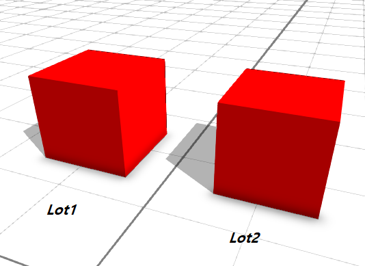
You can use whichever approach suits you best.
What is crucial here is understanding the set() command.
The set() command is not restricted only to Shape attributes; it can be applied to any declared CGA attribute.
Shall we inspect the following code?
attr r = 0

Lot -->
    extrude(10)
    set(r, 1)
    color(r, 0, 0)
    X.
After defining an attribute named r with an initial value, we modify it to 1 inside Lot and then apply it via color().
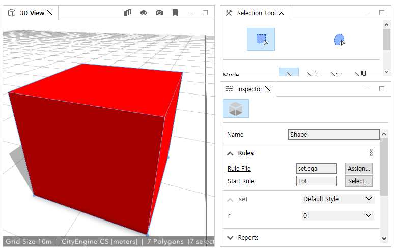
As expected, the color changes to red.
The syntax is fairly simple.
Understanding Attribute Overrides and Inspector Behavior
However, there is a crucial catch that you must be aware of.
Even though the r attribute was clearly changed from 0 to 1 inside the code execution, checking the Inspector panel reveals that the value of r remains at its initially declared value of 0.
This is because when attribute values are dynamically modified within the CGA code context, the changes are not reflected back onto the Inspector panel UI.
And this can lead to confusing scenarios, like the one below.
attr floors = 3
attr floor_height = 3

Lot -->
    set(floor_height, 2)
    extrude(floors * floor_height)
    X.
The code above extrudes a shape by the product of the number of floors and the floor height. However, the floor_height was overridden to 2 right before extrusion.
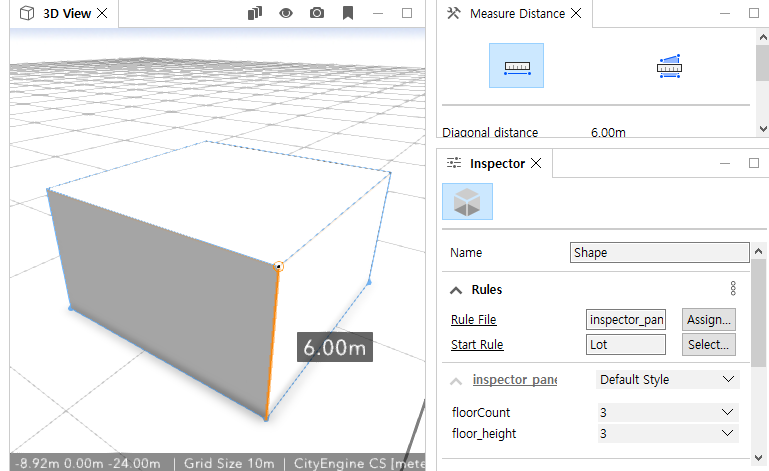
Since we changed floor_height to 2 before extruding, the building height evaluates to 6m.
Yet, the floor_height value in the Inspector panel still displays 3.
Now, try modifying floor_height inside the Inspector panel. The UI value will change, but the actual building height will remain completely unchanged.
This happens because every time that rule is executed, floor_height is forcibly hardcoded back to 2.
To prevent confusion, any attribute values that are modified internally within your code should ideally be hidden from the UI using the @Hidden annotation.
This is especially important when creating reusable procedural assets for other users, since mismatched Inspector values can easily cause debugging confusion.
I added this tip because it's a very common pitfall that people run into when coding CGA rules.
Be sure to keep this in mind.
Specifically, modifying an attribute inside your code prevents those programmatic changes from reflecting in the Inspector UI, rendering UI-based overrides ineffective.
- Learn previous workflow in [056-057] Understanding alignScopeToGeometryBBox() in CityEngine CGA
- Continue learning with [060]CityEngine CGA color() Command Exercises for split.index and Conditional Rules


Comments
Post a Comment
Feel free to leave a comment if you have any questions about Global Mapper or CityEngine. I will get back to you with a sincere response as soon as possible. (Please note that all comments are moderated and manually approved to maintain a high-quality community. Promotional or spam content will not be published.)